Comunicato Stampa
The VLT Writes Its Name
Wonders of Active Optics
13 Agosto 1999
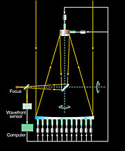
A computer-controlled "Active Optics" system was first developed at ESO in the 1980's. It allows the continuous tuning of the optical system of an astronomical telescope, thus ensuring that it always produces the sharpest possible images of astronomical objects. The first major telescope to profit from this revolution in telescope techniques was the ESO New Technology Telescope (NTT) at the La Silla observatory. Since it began operation in 1990, 75 adjustable supports below the 3.58-m primary mirror, coupled with advanced image analysis and control software, have made this prototype telescope one of the best in the world. Each of the four ESO Very Large Telescope (VLT) Unit Telescopes is equipped with the latest, improved active optics system that controls the primary 8.2-m Zerodur mirror as well as the secondary 1.1-m lightweight beryllium mirror at the top of the telescope structure. This system offers complete control of the optical quality, allowing the VLT to take full advantage of the exceptional atmospheric conditions at Paranal. This is amply confirmed by fine quality of the astronomical observations now performed with the first Unit Telescope, ANTU. In the course of the one-year commissioning period (May 1998 - March 1999), ESO's opticians performed extensive tests and further improvements of the active optics system at ANTU. Here are some interesting examples that illustrate the amazing versatility of this front-line technological system.
Controlling telescope mirrors
Primary mirrors of telescopes with diameters of 1 - 2 metres only can be manufactured so that they are intrinsically rigid. This means that both the shape of the optical surfaces and the relative position of these surfaces do not change significantly when the telescope points to different locations in the sky. To ensure optimum quality of the optics, any variations (the socalled wavefront aberrations ) have to be much smaller than the wavelength of the light that is captured by the telescope. In the visual part of the spectrum (400 - 700 nm), this corresponds to approximately 1/2000 mm, a very small distance indeed.
Each of the four ESO VLT Unit Telescopes has a thin primary mirror with 8.2-m diameter. When the telescope points in different directions, the gravity-induced changes of this giant mirror's shape and position are much larger than the wavelength of visible light. Active optics corrects this in the following way. The images of stars at the focal plane are continuously monitored during the observations by an "image analyser" that detects even the smallest deviations from the optimum. Based on the corresponding signals from this device, the telescope mirrors are then automatically adjusted at regular intervals. In this way, the stellar images always remain optimal, i.e. as round and sharp as possible.
In the VLT, this correction is done, both by deforming the primary mirror and by moving the smaller, rigid 1.1-m secondary mirror of beryllium. The first is done by changing the forces exerted by the 150 individual mirror supports on the rear side of the 8.2-m Zerodur mirror. The outcome of such a correction, which in practice is done at least once a minute, is a perfectly round stellar image. The size of this image is entirely determined by the current atmospheric conditions (referred to as the seeing ).
This procedure is illustrated below by means of a series of video sequences. In some of these, the primary mirror is intentionally deformed by changing the forces of the supports in a specific way. To facilitate the viewing, these sequences are available individually (ESO Press Video eso9940-f ) and combined (ESO Press Video eso9940 ).
Active Optics corrections during observations
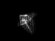
The first sequence initially shows some short-exposure images taken with (intentionally) strongly distorted telescope optics. The stellar images at the focal plane are recorded as strange-looking figures with diameters of the order of 8 arcsec. It may be interesting to note that this is about four times larger than the image size (2 arcsec) recorded already during the very first attempts to obtain a stellar image with VLT ANTU in April 1998, just after the installation of the mirrors in the telescope structure. At that time, apart from some prior mechanical adjustment and alignments and crude focussing, no further corrections had yet been done.
In ESO Press Video eso9940 , a so-called open loop correction is made. It does not use any information from the image analyser. In this case, the forces that are applied to the primary mirror, as well as the optimum position of the secondary mirror, are automatically computed from a table that contains pre-determined values for different inclinations of the telescope tube.
As can be seen, by this simple procedure alone, the full-width-at-half-maximum (FWHM) of short exposure images is now already below one arcsec. An open-loop correction is normally done after the telescope has moved to another position in the sky, to approach the optimum optical quality.
The next step is then the closed-loop correction based on information from the image analyser that continuously monitors the image of a star just outside the field being observed. This reduces the size of the image to the minimum possible, as set by the atmospheric turbulence (seeing). In practice, this may be as small as 0.25 arcsec FWHM, even for exposures lasting several minutes.
Distorted images
By changing the shape of the primary mirror and the position of the secondary mirror, the VLT Active Optics system can generate stellar images with a large variety of geometrical shapes. The next examples illustrate some of the virtually unlimited possibilities and hence the complete control and superior performance of this VLT subsystem, that has now been achieved.
Astigmatic lines
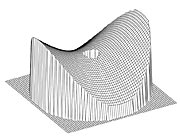
ESO Press Video eso9940 displays a sequence with astigmatic images . They are created by introducing a saddle shape deformation in the primary mirror, cf. ESO Press Photo eso9940c . This increases the mirror surface curvature in one direction and decreases it in the perpendicular direction.
In this particular example, the saddle shape deformation of the ANTU 8.2-m primary mirror has a peak-to-valley variation of only 36 µm (1 µm = 0.001 mm). That is, the mirror is forced upwards by 18 µm at two opposite points at the edge and 18 µm downwards at two points 90° removed from the first ones, i.e. much more than the wavelength of visible light (approx. 0.5 µm). The maximum forces needed to generate these mirror deformations are about 50 Newton. The range of forces at the disposal of the VLT Active Optics System is ten times larger than that. Therefore, with the maximum force applied, the vertical deviation from the optimum mirror surface would be of the order of 0.2 mm, a truly enormous amount for an optical surface.
The resulting image of a star looks like a long rectangle with rounded edges. The length is approximately 16 arcsec.
The secondary mirror is now moved along the common optical axis towards the primary mirror. There will be a position, where the stellar image is more or less in focus (as narrow as posible) in one direction, but not in the perpendicular direction. It looks like a pencil; this is called an astigmatic line .
If the secondary mirror is now moved in the other direction, it will reach another position where the opposite is true. Thus, when the primary mirror is saddle-shaped, the stellar image can be in focus in either of the perpendicular directions, depending on the actual distance between the mirrors. The intermediate position, where the resulting stellar image is roughly square is therefore a "best-focus" compromise.
This sequence is also a demonstration of a simple test to detect the error of astigmatism in an optical system, caused by one of the mirrors having a (slight) saddle shape. If this is so, the orientation of the elongation of the resulting image of a point-like light source (here a star) will change by 90°, when passing through the "best focus".
Images with six-fold symmetry
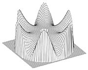
The saddle shape deformation described above has two "high" and two "low" points along the mirror periphery. It is also possible to generate a deformation in which six "high" and six "low" points are separated by 30°, cf. ESO Press Photo eso9940d ; in that case the resulting images will have a six-fold symmetry . At the "best focus" at the beginning of the sequence, this pattern is hardly detectable. However, when the the secondary mirror is moved up and down, thereby "defocussing" the image, this symmetry becomes well visible.
During the sequence shown in ESO Press Video eso9940 , the secondary mirror is first moved in one direction along the optical axis and then back to the "best focus" position, then to the other direction and finally again back to the "best focus" position; this sequence is repeated twice for clarity. As in the case of astigmatism, the lines rotate when one goes from one side of the best focus to the other side. However, the rotation angle is now only 30°, not 90° as in the case of astigmatism.
Rotating crosses
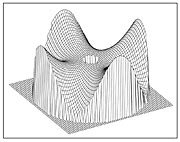
In ESO Press Video eso9940 , cross-like stellar images with a four-fold symmetry are generated by introducing a deformation of the primary mirror with four "high" and four "low" points at the mirror periphery (i.e., 45° apart, cf. ESO Press Photo eso9940e ) and defocussing by moving the secondary mirror towards or away from the primary mirror. Then, maintaining the position of the secondary mirror, the deformation of the primary mirror is "rotated" by changing the support forces so that the "high" and "low" points shift along the mirror periphery in steps of approximately 20°.
As a consequence, the cross-like stellar images with their four-fold symmetry now rotate around their centres by 20° with each step. This spectacular effect, where the images all rotate around their individual centres, cannot be achieved by rotating the light detector in the focal plane, since all stellar images would then rotate around one common centre in the field.
Letters
The ultimate application of this kind of mirror deformations and shifts is the generation of arbitrary patterns . The type of patterns that can be made is restricted by the fact that even a comparatively thin mirror like the VLT main mirror can only be deformed inside certain limits. Within the given range of forces available, deformations can only be generated for geometrical shapes that are comparatively smooth.
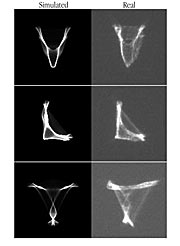
The name of the VLT may be written in the sky with images that ressemble the shapes of the letters "V", "L" and T", as generated from a force pattern with no more than eight extreme points at the edge or three lines ("ridges" and/or "valleys") across the mirror surface. The sequence in ESO Press Photo eso9940f shows these three letters, as generated by a computer simulation. They should look very much like the real images generated by the active optics system at the telescope, if the same forces are applied, but they are of course without the disturbing effects of the atmosphere.
ESO Press Video eso9940 then shows the real, distorted images, obtained at ANTU and affected by quickly changing atmospheric turbulence. The comparison in ESO Press Photo eso9940g of the simulated and the real letters is impressive - even minor details are well reproduced! This demonstrates how well the VLT active optics is now understood and can be controlled .
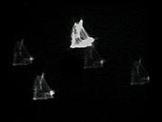
The next sequence (ESO Press Video eso9940 ) shows the real images, now with several stars in the field. The integration time was 0.8 seconds. This is longer than the time scale of atmospheric turbulence and the additional deformation of the stellar images due to the seeing is practically the same for all of the images. If a shorter integration time would have been used, the images may have looked more different, especially those that are farthest apart. This is because of the relatively small size of the air cells that cause the seeing effect, and whereby the light from different stars in the field is subject to different atmospheric disturbances.
Combined Video Clip
This is the caption to ESO Press Photos eso9940 and ESO Press Video eso9940-g . They may be reproduced, if credit is given to the European Southern Observatory.
ESO expects to issue a Technical Video with a technical description of the VLT Active Optics System and including these sequences in September 1999.
Sul Comunicato Stampa
| Comunicato Stampa N": | eso9940 |
| Legacy ID: | Photo 34a-g/99 |
| Nome: | Active Optics, Very Large Telescope |
| Tipo: | Unspecified : Technology : Observatory |
| Facility: | Very Large Telescope |
Our use of Cookies
We use cookies that are essential for accessing our websites and using our services. We also use cookies to analyse, measure and improve our websites’ performance, to enable content sharing via social media and to display media content hosted on third-party platforms.
ESO Cookies Policy
The European Organisation for Astronomical Research in the Southern Hemisphere (ESO) is the pre-eminent intergovernmental science and technology organisation in astronomy. It carries out an ambitious programme focused on the design, construction and operation of powerful ground-based observing facilities for astronomy.
This Cookies Policy is intended to provide clarity by outlining the cookies used on the ESO public websites, their functions, the options you have for controlling them, and the ways you can contact us for additional details.
What are cookies?
Cookies are small pieces of data stored on your device by websites you visit. They serve various purposes, such as remembering login credentials and preferences and enhance your browsing experience.
Categories of cookies we use
Essential cookies (always active): These cookies are strictly necessary for the proper functioning of our website. Without these cookies, the website cannot operate correctly, and certain services, such as logging in or accessing secure areas, may not be available; because they are essential for the website’s operation, they cannot be disabled.
Functional Cookies: These cookies enhance your browsing experience by enabling additional features and personalization, such as remembering your preferences and settings. While not strictly necessary for the website to function, they improve usability and convenience; these cookies are only placed if you provide your consent.
Analytics cookies: These cookies collect information about how visitors interact with our website, such as which pages are visited most often and how users navigate the site. This data helps us improve website performance, optimize content, and enhance the user experience; these cookies are only placed if you provide your consent. We use the following analytics cookies.
Matomo Cookies:
This website uses Matomo (formerly Piwik), an open source software which enables the statistical analysis of website visits. Matomo uses cookies (text files) which are saved on your computer and which allow us to analyze how you use our website. The website user information generated by the cookies will only be saved on the servers of our IT Department. We use this information to analyze www.eso.org visits and to prepare reports on website activities. These data will not be disclosed to third parties.
On behalf of ESO, Matomo will use this information for the purpose of evaluating your use of the website, compiling reports on website activity and providing other services relating to website activity and internet usage.
Matomo cookies settings:
Additional Third-party cookies on ESO websites: some of our pages display content from external providers, e.g. YouTube.
Such third-party services are outside of ESO control and may, at any time, change their terms of service, use of cookies, etc.
YouTube: Some videos on the ESO website are embedded from ESO’s official YouTube channel. We have enabled YouTube’s privacy-enhanced mode, meaning that no cookies are set unless the user actively clicks on the video to play it. Additionally, in this mode, YouTube does not store any personally identifiable cookie data for embedded video playbacks. For more details, please refer to YouTube’s embedding videos information page.
Cookies can also be classified based on the following elements.
Regarding the domain, there are:
- First-party cookies, set by the website you are currently visiting. They are stored by the same domain that you are browsing and are used to enhance your experience on that site;
- Third-party cookies, set by a domain other than the one you are currently visiting.
As for their duration, cookies can be:
- Browser-session cookies, which are deleted when the user closes the browser;
- Stored cookies, which stay on the user's device for a predetermined period of time.
How to manage cookies
Cookie settings: You can modify your cookie choices for the ESO webpages at any time by clicking on the link Cookie settings at the bottom of any page.
In your browser: If you wish to delete cookies or instruct your browser to delete or block cookies by default, please visit the help pages of your browser:
Please be aware that if you delete or decline cookies, certain functionalities of our website may be not be available and your browsing experience may be affected.
You can set most browsers to prevent any cookies being placed on your device, but you may then have to manually adjust some preferences every time you visit a site/page. And some services and functionalities may not work properly at all (e.g. profile logging-in, shop check out).
Updates to the ESO Cookies Policy
The ESO Cookies Policy may be subject to future updates, which will be made available on this page.
Additional information
For any queries related to cookies, please contact: pdprATesoDOTorg.
As ESO public webpages are managed by our Department of Communication, your questions will be dealt with the support of the said Department.


